Obstacle Surfaces
MSA – Minimum Sector Altitude (applies to instrument airports)
The first part of an approach flight to an instrument airport is called Initial Approach, and here the lowest flying altitude is determined by the MSA surface. This surface is based on the locator for the respective runway and is a circle with a radius of 55 km. This is divided into four quadrants; northwest, northeast, southwest and southeast. Each quadrant is given 300 meters margin to the highest obstacle. Example: The northeast quadrant has a highest obstacle of 155 meters above sea level. The lowest flying altitude in this quadrant towards to the locator will then be 155m + 300m = 455 meters. LFV has MSA maps for all instrument airports.
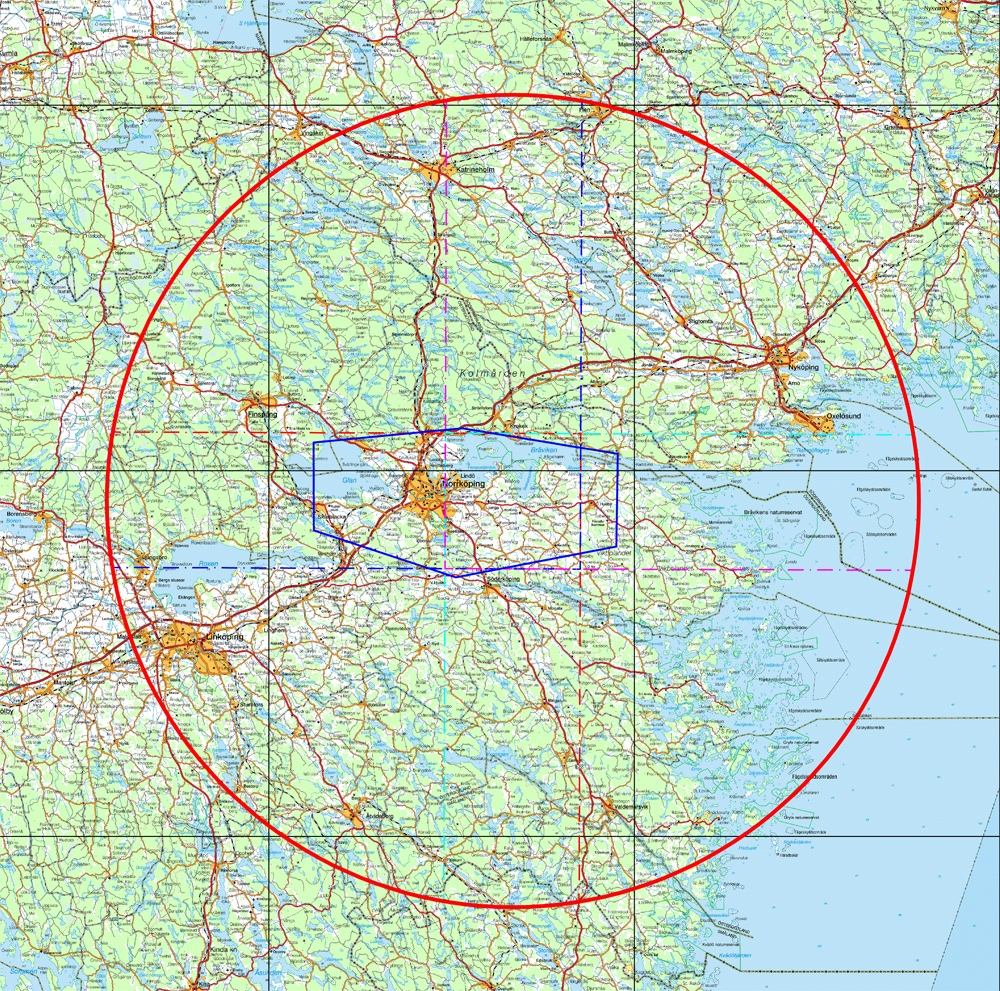
Map: The circle shows the MSA surface for approach path 27,
Norrköping Airport (click on the image for a larger map)
Holding, Racetrack, Intermediate, Final, Missed Approach (applies to instrument airports)
Once the approach has begun, air traffic control may place aircraft in a waiting position, i.e. “holding”, due to the traffic situation. This is set in the vicinity of the airport, usually by a radio beacon. When the aircraft is ready for landing it flies out from the beacon and turns back toward the field — racetrack. With the landing field straight ahead the aircraft enters intermediate approach, and then in the final stage is in final approach. If the runway cannot be seen at the lowest altitude (minimum), approach must be interrupted, making a so-called missed approach. A special approach is made so that approach is made to a runway, to then go around the airfield with ground visibility and land on a different runway, which is called “circling”. Common to all surfaces is that the closer the plane gets to the runway’s imagined extension line, the worse the chances are for erecting tall obstacles. Other ways to make approaches are radar guidance and STAR (Standard Arrival Route) approach. In both of these cases a shorter route toward the field is flown. See map on SID/STAR below. In all these occurrences a required obstacle margin must be maintained; LFV has all the data for all of these obstacle surfaces.
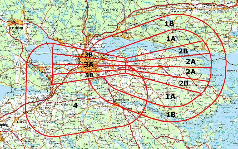
Map: Obstacle surfaces for racetrack, approach and missed approach for path 27, Norrköping Airport (click on the image for a larger map)
Explanation of obstacle surfaces:
1A Racetrack surface, primary*
1B Racetrack surface secondary**
2A Intermediate approach surface, primary*
2B Intermediate approach surface, secondary**
3A Final approach/Initial Missed Approach surface, primary*
3B Final approach surface, secondary**
4 Missed approach surface
In addition there is the circling surface closest to the airfield which in principle is contained within the above surfaces.
*) Primary surface has a fixed obstacle margin
**) Secondary surface has an obstacle margin gradually reduced toward the outer edge
Green approaches
What are known as “green approaches” are now being developed, in which the shortest possible route is flown, with the engines on idle. This type of approach is being tested at a number of airports and conserves fuel and reduces environmental impact. These are the flight paths of the future and even now how these obstacle surfaces are going to appear must be taken into account. If tall obstacles are located close to the airport, there is a risk that future possibilities for green approaches will be ruled out.

Illustration: Traditional approach (here illustrated in red) compared with green approach
ICAO Annex 14 surfaces
(applies to everything from instrument airports to small grass field)
In the immediate vicinity of the airport there are obstacle surfaces that guarantee that airplanes and other aircraft can ascend from and descend to the runway without coming too close to underlying obstacles. There are various surfaces, for example start, climb, and approach surfaces that regulate the obstacle clearance in the extension of the runway. Horizontal surface and conic surface regulate obstacle clearance around the entire field. In contrast to racetrack and approach surfaces, these surfaces affect both visual and instrument air navigation and are the very basis of an airport’s obstacle surfaces.
The majority of these surfaces are found at the Swedish Transport Administration website (webpage in Swedish). LFV takes these surfaces into consideration in our airport obstacle analyses.

Map: ICAO Annex 14 surfaces where the arrow-shaped surfaces are climb/approach surfaces and the oval surfaces are horizontal/conic surfaces (click on the image for a larger map).
SID (Standard Instrument Departure) och Omni Directional Departure
At large airports there is usually a pre-defined outbound route for the pilot to fly, a Standard Instrument Departure (SID), to lead air traffic away from the airport. At all airports Omni Directional Departure may be used, which means that it is possible to fly out in all directions and always be free from obstacles. In all these events a mandatory obstacle margin must be maintained. LFV has all the data for all of these obstacle surfaces.

Map: SID/STAR for Luleå/Kallax Airport
Dotted line = STAR (incoming traffic) Solid line =SID (outgoing traffic)